The magnetization of any given point on the sheet varies, so the extension and contraction is not uniform. A transformer core is made from many sheets of special steel to reduce losses and moderate the ensuing heating effect. The extensions and contractions are taking place erratically all over a sheet and each sheet is behaving erratically with respect to its neighbor, so you can see what a moving, writhing construction it is when excited. These extensions are miniscule proportionally and therefore not normally visible to the naked eye. However, they are sufficient to cause a vibration, and consequently noise. Applying voltage to a transformer produces a magnetic flux, or magnetic lines of force in the core. The degree of flux determines the amount of magnetostriction and hence, the noise level.
Why not reduce the noise in the core by reducing the amount of flux? Transformer voltages are fixed by system requirements. The ratio of these voltages to the number of turns in the winding determines the amount of magnetization. This ratio of voltage to turns is determined mainly for economical soundness. Therefore the amount of flux at the normal voltage is fixed. This also fixes the level of noise and vibration. Also, increasing (or decreasing) magnetization does not affect the magnetostriction equivalently. In technical terms the relationship is not linear.
Impedance is the current limiting characteristic of a transformer and is expressed in percentage. It is used for determining the interrupting capacity of a circuit breaker or fuse employed to protect the primary winding of a transformer. The impedance (or resistance to current flow) is important and used to calculate the maximum short circuit current which is needed for sizing, circuit breakers and fuses. This percentage represents the amount of normal rated primary voltage which must be applied to the transformer to produce full rated load current when the secondary winding is short circuited. The maximum short circuit current that can be obtained from the output of the transformer is limited by the impedance of the transformer and is determined by multiplying the reciprocal of the impedance times the full load current.
High and Low Impedance Transformers:
High impedance transformers have a lower fault or short circuit current and have no need for high AIC rated breakers. However, they will have a higher voltage drop or regulation.
Low Impedance transformers on the other hand have a lower voltage drop or regulation but have a higher fault or short circuit current and will need higher AIC rated breakers.
Why is impedance given in a percentage?
The percentage impedance of a transformer (Z%) is the voltage drop on full load due to the winding resistance and leakage reactance expressed as a percentage of the rated voltage.
Electrical impedance of the load is expressed in ohms, and the relationship between the current and the voltage in the circuit is controlled by the impedance in the circuit. In general, impedance has a complex value, which means that loads generally have a resistance to the source that is in phase with a sinusoidal source signal and reactance that is out of phase with a sinusoidal source signal. The total impedance is the vector sum of the resistance and the reactance. The impedance is measured by shorting the low voltage terminals. With low voltage windings shorted, a voltage at the rated frequency is applied to the high voltage windings until full load current is circulated in low voltage windings. The ratio of voltage applied to circulate full load current to the primary voltage is the percentage impedance of the transformer.
The percentage impedance of the transformer is calculated as: Z%= (Impedance Voltage/Rated Voltage)*100
Thus a transformer with a primary rating of 110V which requires a voltage of 10V to circulate the rated current in the short-circuited secondary would have an impedance of 9%.
What Causes Transformer Noise?
Transformers, by design, produce an audible “hum” caused by vibrations in the electrical steel. The vibrations are caused by a property known as “magnetostriction” which causes the core steel to change its shape and dimension while magnetized. As the vibration increases, the ‘humming” sound levels rise.
Why is it Important to Reduce Noise Levels?
For all units, MGM adheres to NEMA standards that specify sound levels depending on KVA. Additionally, there are special applications where increased noise reduction is critical. Examples include hospitals, high-rise buildings, schools, offices, libraries or other uses where transformers are placed near their loads in noise-sensitive environments.
How Does MGM Reduce Noise Levels?
MGM has a proprietary noise-reduction design that uses techniques to minimize magnetostriction-caused humming. Our design adjusts the clamping force, core material, core design, and installs anti-vibration pads throughout the unit. In addition to design, transformer placement is critical, so MGM offers support services to ensure acoustical principles are considered during installation.
How Does MGM Test Noise Levels?
Per the NEMA testing standards, MGM tests each unit at its rated frequency & voltage under no-load conditions. The testing room is approximately 10 feet larger than the transformer on all sides with an ambient sound level of 5 db. Five sound readings are taken with an approved / calibrated sound meter one foot from each side of the transformer enclosure and one foot above the enclosure. The sound rating is the average of these five readings.
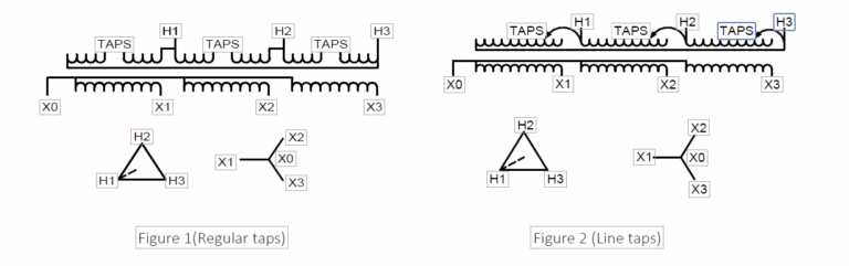
Sometimes the input voltage may be different than the nominal voltage on the nameplate, which results in output voltages that are different than what is required. In these situations, the transformer should be designed with taps which adjust the turn ratio and maintain the required output voltage. On our standard transformers, two taps are placed ‘above’ full capacity and four taps are placed ‘below’ full capacity taps at 2.5% increments. These are known as 2AFCAN and 4FCBN. The number of taps and their percentages may vary based on the KVA size of the transformer; the higher KVA transformers may have few taps at higher percentages or in some cases no taps at all.
Taps Construction
Tap terminals can be either loop type or welded brazed terminal type. For the loop taps, coil conductor is brought out,stripped of its insulation, and formed as a loop for suitable hardware size. Terminal type taps are simply brazed to the coil conductor at the desired location.
Taps location
The first method of providing taps is to have either loop or welded terminal type on the last layer of the coil away from the finish line. There will be one break usually between taps #4 and #5 on the tap section. A jumper will be provided for each coil to select desired input voltage as specified on the nameplate. See Figure 1.
The second method of providing taps is to have either loop or welded terminal type at the end of the coil without any break in between them. In this case the last tap (usually #7) will be the finish line of the coil. Using this method of taps, the delta or wye connection of input side will be closed right at the tap based on the nameplate. This style of taps is known as “End of the coil taps or the line taps”. See Figure 2. In method 1, the tap jumpers are used to connect two of the tap terminals of the same coil together while on the method 2 (End of the coil taps or the line taps) the tap jumper is used to connect only one of the tap terminal to the corresponding phase terminal per the desired voltage according to the nameplate.
Insulating and isolating transformers are identical. These terms are used to describe the separation of the primary and secondary windings. A shielded transformer includes a metallic shield between the primary and secondary windings to attenuate (lessen) transient noise.
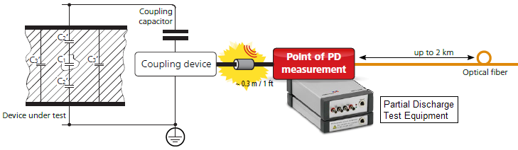
Corona (not the beer) is the generic name for electrical discharge that occurs in electrical insulation as a result of high velocity ionization under the influence of an electric field that exceeds the dielectric strength of the insulation. Corona and the term partial discharge are used interchangeably when referring to this phenomenon in transformers. The partial discharge terminology is preferred since it most accurately describes the occurrence. Much has been written concerning the cause of partial discharges. Some of the common conditions that can initiate partial discharges are:
- Improper site and/or weather conditions with humid/dusty environments, poor or no maintenance procedures.
- Improper processing or drying of the insulation.
- Over-stressed insulation due to lack of proper recognition of the voltage limitation of the insulation.
- High stress areas on conducting parts which can be caused by sharp edges on either the conducting parts or ground plane.
The effect of partial discharge in a transformer is twofold.
- One effect is that the ion and electron bombardment can be damaging to the insulation and shortens the life of the transformer.
- The other effect is the transient currents produced due to partial discharge may interfere with electrical communications.
Partial discharge is defined as an optional test per IEEE C57.12.01.2015. MGM, for its own research and continual improvement performs this test periodically on a first design and or on prototypes. We also offer customer witness testing when specified at the time of order.
MGM Transformer Company has been aware of the consequences of partial discharge in transformers for many years and has developed drying and processing procedures as well as insulation systems that virtually eliminates the presence of damaging partial discharges within our coils. The general procedure for partial discharge testing is to raise the voltage to 1.8 times the rated voltage and hold for a minimum of 30 seconds and then reduce the voltage to a level equivalent to 1.3 times and maintain it for 3 minutes and measure the partial discharge levels. The ambient levels of the instrumentation shall be considered when determining the final value of partial discharge. The maximum acceptable levels of partial discharge for resin-encapsulated windings is 50 pC (picoCoulumbs).
Single phase transformers can be used in parallel only when their voltages are equal. If unequal voltages are used, a circulating current exists in the closed network between the two transformers which will cause excess heating and result in a shorter life of the transformer. In addition impedance values of each transformer must be within 7.5% of each other.
So which is better? Copper or aluminum windings?
Believe it or not, transformers wound with aluminum or copper wire have similar losses and performance. The choice of using copper or aluminum windings depends upon the application and the individual preferences of the person specifying the transformer. Aluminum’s perceived problem dates to the 1960’s when connection problems caused several fires. There were never any problems with the actual aluminum wire. Modern, secure methods for connecting aluminum wire have been developed and are widely used. New methods of connections pierce the aluminum oxide layer in such a way that they remain gas tight to prevent further oxidation.
The type of winding material does not affect the  transformer’s reliability. A transformer’s life is defined by the life of its insulation system. Because aluminum-wound and copper-wound units run at equivalent operating temperatures, the insulation systems age at the same rate for each design.
An advantage of aluminum windings is weight. Aluminum transformers weigh considerably less than copper transformers. This is important in high-rise office buildings with serious square foot weight limits per floor.
Another advantage of aluminum wire is cost. Transformers wound with aluminum wire have considerably less cost than their copper equivalent with very similar performance.
The bottom line:
Improvements in technology regarding the use of aluminum in transformers have made aluminum-wound transformers the ideal choice for today’s applications. Here at MGM we can supply both windings with our transformers but most of the units we sell are aluminum-wound. Customers get the same performance with less cost so aluminum is a more common choice.
Typically the output winding is wound first and is therefore closest to the core. When used as exciting winding a higher inrush current results. In most cases the inrush current is 10 to 12 times the full load current for 1/10 of a second. When the transformer is reverse fed the inrush current can be up to 16 times greater. In this case a bigger breaker with a higher AIC rating must be used to keep the transformer online.
TTR stands for Transformer Turns Ratio. The function of a transformer is to transform power from one voltage level to another. The ratio test ensures that the transformer windings have the proper turns to produce the voltages required. For example a 480V primary to 240V secondary will have a ratio of 2:1 with a TTR value of 2.
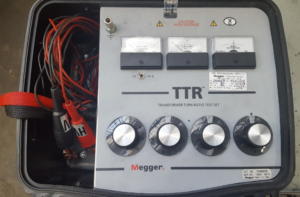

The Standards state that when rated voltage is applied to one winding of the transformer all the other rated voltages at no load shall be correct within one half of one percent of the nameplates readings. It also states that all tap voltages shall be correct to the nearest turn if the volts per turn exceed the one half of one percent of the desired voltage. The ratio test verifies that these conditions are met.
The calculated ratios for a transformer with a rated primary phase voltage of 12470 with 2.5% taps above and below rated voltage and a rated secondary phase voltage of 480 are shown below. The ratio limits given permit a tolerance of one half of one percent from the rated voltage.
Ratio Limits (calculated by dividing the primary voltage by the secondary voltage):
| Voltage | Ratio | Upper Limit | Lower Limit |
|---|---|---|---|
| 13095 | 27.281 | 27.417 | 27.145 |
| 12780 | 26.625 | 26.758 | 26.492 |
| 12470 rated | 25.979 | 26.109 | 25.849 |
| 12160 | 25.333 | 25.460 | 25.207 |
| 11850 | 24.687 | 24.810 | 24.564 |
Taps are normally in the primary winding to adjust for varying incoming voltage. If the transformer is reverse fed, the taps are on the output side and can be used to adjust the output voltage.
MGM uses a powder coating paint process. Powder coating provides a long-lasting, economical and durable finish with a range of color options available for nearly any type of metal. In addition, a powder coated surface will be more resistant against scratches, chipping, wear, and fading compared to other type of finishes.
MGM’s standard paint system utilizes TGIC  Polyester powder coatings designed for exterior exposure and offers excellent weather resistance from a single coat finish, has good chemical resistance to splash/spillage, fumes and immersion in neutral, fresh and salt water. Standard color used on all dry-type and liquid-filled transformers is ANSI 61, a light gray color. We have two lines one for ANSI 61 and one for ANSI 49. In addition to the colors listed above, the factory can supply any RAL colors or if we are supplied with a sample paint chip of the color to match.
Optional Premium System (Provided when specified on order):
For added protection with increased impact resistance and additional corrosion protection, MGM can offer an optional premium paint system. This system consists of a base coat of the epoxy coating, as described above, followed by additional coat of a high build polyurethane coating ( 5 MIL or 125 Microns). This polyurethane coating has excellent color, UV protection and gloss retention during extended service periods. The multiple coat premium paint system results in a high performance, corrosion resistant, system with excellent appearance and durability.
Advantages of Powder Coating:
- Powder coatings contain no solvents and release little or no amount of Volatile Organic Compounds (VOC) into the atmosphere. Thus, there is no need for finishers to buy costly pollution control equipment. Companies can comply more easily and economically with the regulations of the S. Environmental Protection Agency.
- Powder coatings can produce much thicker/dense coatings than conventional liquid coatings without running or sagging.
- Powder coated items generally have fewer appearance differences than liquid coated items between horizontally coated surfaces and vertically coated surfaces.
- A wide range of specialty effects are easily accomplished using powder coatings that would be impossible to achieve with other coating processes.
- Curing time is significantly faster with powder coating than with liquid coating.
The voltage regulation is defined as the change in the magnitude of receiving and sending voltage of the transformer. The voltage regulation determines the ability of the transformer to provide the constant voltage for variable loads. When the transformer is loaded with continuous supply voltage, the terminal voltage of the transformer varies. The variation of voltage depends on the load and its power factor.
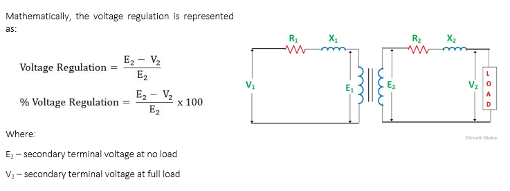
Let us understand the voltage regulation by taking an example explained below:
If the secondary terminals of the transformer are open circuited or no load is connected to the secondary terminals, then no current flows through it. If no current flows through the secondary terminals of the transformer, the voltage drops across their resistive and reactive load become zero. The voltage drop across the primary side of the transformer is negligible.
If the transformer is fully loaded, i.e., the load is connected to their secondary terminal, the voltage drops appear across it. The voltage regulation values vary based on type of loads connected across the transformer like resistive, inductive or capacitive. The value of the voltage regulation should always be less for the better performance of transformer.
No exposition on transformer regulation could be called complete without mention of an unusual device called a ferroresonant transformer. “Ferro resonance” is a phenomenon associated with the behavior of iron cores while operating near a point of magnetic saturation (where the core is so strongly magnetized that further increases in winding current results in little or no increase in magnetic flux).
Insulation class was the original method used to distinguish insulating materials operating at different temperature levels. Letters were used for different designations. Letter classifications have been replaced by insulation system temperatures in degrees celsius. The system temperature is the maximum temperature at the hottest spot in the winding.
No. This can be compared with an ordinary light bulb. The filament temperature of a light bulb can exceed 2000 degrees yet the surface temperature of the bulb is low enough to permit touching with bare hands.
Yes. This system can be used for either grounding or developing a fourth wire from a three phase 3 wire. (neutral)
All MGM transformers are certified by the Canadian Standards Association. They have been designed and tested in accordance with the latest specifications.
Polarity is the instantaneous voltage obtained from the primary winding in relation to the secondary winding. Transformers 600 volts and below are normally connected in additive polarity. This leaves one high voltage and one low voltage terminal unconnected. When the transformer is excited, the resultant voltage appearing across a voltmeter will be the sum of the high and low voltage windings. This is useful when connecting single phase transformers in parallel for three phase operations. Polarity is a term used only with single phase transformers.
To determine the required amp rating breaker to use, follow these simple steps:
- Click calculator here, or on the main navigation bar on the left.
- Input rated KVA and primary voltage of your transformer and click calculate.
- Take the resulting amperage rating and multiply it by a minimum of 1.2 (recommended 1.4) do determine the amperage required.
- Breakers are made in standard ratings, you should purchase a breaker rated equal to or higher than your requirements.
When reverse feeding a transformer the breaker required will be larger due to reduced primary voltage. Follow the same procedure to determine your breaker requirements.
NOTE: In case of discrepancy, provisions of NEC 450-3 and/or other local/national codes shall prevail over the above general guidelines.
Yes, but the load can not exceed the rating per phase and the load must be balanced. (KVA/3 per phase)
For example: A 75 kVA 3 phase transformer can be loaded up to 25 kVA on each secondary. If you need a 30 kVA load, 10 kVA of load should be supplied from each secondary.
The heat a transformer generates is dependent upon the transformer losses. To determine air conditioning requirements multiply the sum of the full load losses (obtained from factory or test report) of all transformers in the room by 3.41 to obtain the BTUs/hour.
For example: A transformer with losses of 2000 watts will generate 6820 BTUs/hour.
In most cases the enclosure of the transformer is grounded for safety reasons. However, a transformer will function properly without being grounded. Be sure to research all grounding requirements for your specific application against the NEC (National Electrical Code) as well as any local electrical codes.
All transformers work on the same principles of electromagnetic induction and are primarily used to change voltages to serve different purposes within the power system. Power and Distribution transformers, however, serve two different purposes and therefore require different classifications.
Power transformers are used in high voltage ![]() transmission networks for step-up and step-down applications (400 kV, 200 kV, 110 kV, 66kV, 33kV) and are generally rated above 200MVA. When voltage is generated (e.g., nuclear, hydro, renewables) it is usually stepped up to a very high voltage to minimize I2R losses that occur in transmission lines. Since Power transformers are used in Transmission networks and are not directly connected to end consumers (e.g., commercial, Industrial, residential), load fluctuations are minimal. They are loaded 24 hours a day and designed for maximum efficiency at full load.
transmission networks for step-up and step-down applications (400 kV, 200 kV, 110 kV, 66kV, 33kV) and are generally rated above 200MVA. When voltage is generated (e.g., nuclear, hydro, renewables) it is usually stepped up to a very high voltage to minimize I2R losses that occur in transmission lines. Since Power transformers are used in Transmission networks and are not directly connected to end consumers (e.g., commercial, Industrial, residential), load fluctuations are minimal. They are loaded 24 hours a day and designed for maximum efficiency at full load.
Distribution transformers are used in lower voltage distribution networks for end-user connectivity (11kV, 6.6 kV, 3.3 kV, 480V, 208V) and are generally rated less than 200 MVA.
Distribution Transformers are used at the  distribution level where the secondary voltage is typically delivered to the end consumer. Because of the voltage drop that occurs when traveling long distances, Distribution transformers are generally located in close proximity to the end user. MGM Transformer Company is the leader in manufacturing distribution transformers up 10MVA in both dry type and liquid substation.
Distribution transformers are connected to end-users who don’t operate at full load all the time, so they are designed for maximum efficiency at 50% to 70% load. This explains why the DOE (Department of Energy) efficiency regulations define the maximum efficiency at 50% load for medium voltage distribution transformers and 35 % load for low voltage distribution transformers.
A transformer can’t act as a phase changing device and change single-phase into 3-phase or 3-phase into single phase. So a question frequently asked is: Can a single-phase transformer be used on a three phase source? The answer is YES!
We all pretty much know 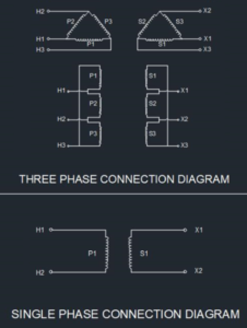 that transformers are constructed as either singe phase or three phase. Voltage transformers, however, can be constructed for connection to not only one-phase or three-phase but for two-phases, six-phases and even elaborate combinations up to 24-phases for some DC rectification transformers. If we take 3 single-phase transformers and connect their primary windings to each other and their secondary windings to each other in a fixed configuration (either delta or wye), we can use the transformers on a three-phase supply.
To make the transformer connections compatible with three-phase supplies we need to connect 3 single-phase transformers together in a particular way to form one Three Phase Transformer.
A three phase transformer or 3φ transformer can be constructed either by connecting together 3 single-phase transformers, thereby forming a so-called three phase transformer bank or by using one pre-assembled and balanced three phase transformer which consists of three windings mounted onto one laminated core.
The advantages of building a single three phase transformer is that for the same kVA rating it will be smaller, cheaper and lighter than three individual single phase transformers connected together because the copper and iron core are used more effectively. The methods of connecting the primary and secondary windings are the same, whether using just one Three Phase Transformer or three separate Single Phase Transformers.
Temperature rise in a transformer is the average temperature of the windings and insulation above the existing ambient temperature. The rating or kVA of a transformer is determined by the allowable operating temperature of its insulation or as more commonly referred to in transformer application, the temperature rise above the ambient temperature. The temperature that the insulation reaches depends upon the load and the ambient temperature surrounding the transformer.
Temperature limits for windings in  transformers with 220 °C insulation have been established as 210°C by ANSI and NEMA standards. This comes from the average winding temperature rise of 150°C plus a 30°C average ambient plus another 30°C hot spot differential. These limits were established to provide normal life expectancy of the insulation.
Transformers are designed to meet their rated kVA and the temperature test is a means to verify that these limits are met. The temperature rise test simulates the rated load on the transformer at the worst case tap connection. There are a few ways manufacturers can do this test but the most common is the short circuit method. This method is done by shorting one winding while circulating full load current in the other winding. The temperature rise is then determined by using thermocouples placed at hot spots in the windings and measuring cold and hot resistance.
Temperature rise tests are an optional test and are usually not performed unless it is specifically required. The standards permit this test to be omitted if results from an essentially duplicate unit have been done.
It should be pointed out that loading a transformer in excess of its temperature limits will result in loss of life. When overloading is required, A.N.S.I. C57.96, Guide for Loading dry distribution and Power Transformers provides loss of life information. ANSI guidelines have data showing that each 10°C above the insulation system shortens the life by half. So, it is important to operate the transformer within its temperature limits to obtain maximum life from the transformer.
BIL is an abbreviation for Basic Insulation Level. Insulation levels in electrical equipment are characterized by the withstand voltages used during the impulse test. Impulse test is a dielectric test which consists of the application of a high frequency steep wave front voltage between windings and between windings and ground. The BIL of a transformer is a method used to specify the magnitude of the voltage surge that a transformer can tolerate without any damage to the windings and live parts of the transformer. When lightning impulse over voltage appears in the system, it is discharged through surge protecting device before the transformer gets damaged. BIL rating specifies the minimum voltage that transformer can withstand under this condition.
The method of testing of the transformer for 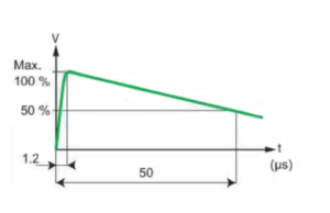 BIL has been defined and set by IEEE and ANSI standards. The wave shape has been also defined which is commonly known as 1.2/50 μs voltage wave. The impulse wave shape shows the magnitude of the voltage in KV (Kilo volts), Rise time (tf, time that takes the voltage rise from zero to its peak value in μs (Micro seconds)),and duration of the surge (T) sometime referred as Tail time (time that takes the voltage drop to 50% of its peak value in μs (Micro seconds).
This test is done with the initial transformer design to validate the integrity of the insulation and its high frequency surge withstand capability. It is considered one of the design tests for any transformer and needs not to be repeated with every transformer manufactured. However, a quality control impulse test (QC impulse test or production impulse test) is offered as an optional test whenever required. Design impulse test consists of a reduced voltage, 2 chopped wave, and a full voltage impulse applied to the transformer. Voltage and current wave shapes are captured during the above tests for comparison. Any deviation from the reduced wave to full voltage wave shape should be studied. In general, they should be very close to each other. Any new bump in the full wave can be considered as a failure point. Based on the location of the bump, an educated guess can be made as where the failure has occurred. After subjecting the transformer to above voltage surge tests, transformer should pass hi pot test at 60Hz. and double induced voltage test 400 Hz.
During quality control, impulse-only full voltage surge is applied to all of the bushings or the terminals of the transformer before hi pot and double induced test is performed.
When voltage is introduced to one coil, called the primary, it magnetizes the iron core. A voltage is then induced in the other coil, called the secondary or output coil. The change of voltage (or voltage ratio) between the primary and secondary depends on the turns ratio of the two coils.
Put the transformer in a room in which the walls and floor are massive enough to reduce the noise to a person listening on the other side. Noise is usually reduced (attenuated) as it tries to pass through a massive wall. Walls can be of brick, steel, concrete, lead, or most other dense building materials.
Put the object inside an enclosure which uses a limp wall technique. This is a method which uses two thin plates separated by viscous (rubbery) material. As the noise hits the inner sheet some of its energy is used up inside the viscous material. The outer sheet should not vibrate.
Build a screen wall around the unit. This is cheaper than a full room. It will reduce the noise to those near the wall, but the noise will get over the screen and fall elsewhere (at a lower level). Screens have been made from wood, concrete, brick and with dense bushes (although the latter becomes psychological)
Do not make any reflecting surface coincident with half the wave length of the frequency. What does this mean? Well, every frequency has a wave length. To find the wave length in air, for instance, you divide the speed of sound, in air (generally understood as 1130 feet per second) by the frequency. If a noise hits a reflecting surface at these dimensions it will produce what is called a standing wave. Standing waves will cause reverberations (echoes) and an increase in the sound level. If you hit these dimensions and get echoes you should apply absorbent materials to the offending walls (fiberglass, wool, etc.)
In some cases, transformers can be operated at voltages below the nameplate rated voltage. In NO case should a transformer be operated in excess of its nameplate rating unless taps are provided for this purpose. When operating below the rated voltage the KVA capacity is reduced correspondingly.
All Dry-type and Liquid filled distribution transformers manufactured by MGM Transformer Company are PCB (polychlorinated biphenyl) free at the time of shipment.
MGM is mainly known for its dry type transformers, but we also make liquid filled transformers and we can design and build with any fluid on the market. Dry type transformers are, you guessed it “dry”, so they are cooled by the air that passes through it.
Liquid Transformers are cooled by the fluid that it’s immersed in. Fluid is used to cool the windings and provide optimal performance in the manner below.  The bottom of the tank is where the fluid is at its lowest temperature. The fluid flows up through the windings and is heated by the windings which in turn makes it rise to the top. At the top of the tank the fluid is at its hottest temperature and exits the tank to go through a series of radiators where it’s cooled and then flows back down to the bottom of the main tank. This process is continuous and can be aided by fans mounted on the radiators to cool the radiators at an even faster rate. There are several types of fluids offered but today’s feature is on the PCB filled transformers that are still floating around (no pun intended).
Polychlorinated biphenyls (PCBs) were used as transformer oil, since they have high dielectric strength and are not flammable. Unfortunately, they are also toxic, bio-accumulative, not at all biodegradable, and difficult to dispose of safely. When burned, they form even more toxic products, such as chlorinated dioxins and chlorinated dibenzofurans.
Mixtures of polychlorinated biphenyls (PCB’s) were manufactured commercially in the US until 1977 and used as transformers fluids because of their nonflammable nature and chemical stability.
PCBs were widely used for about fifty years and produced under a variety of trade names, the most common of which were Askarel® and Pyranol®. Although chemically stable, PCBs would only slowly biodegrade. That is that they tended to persist in nature as opposed to decomposing into basic elements. There were numerous health studies conducted that documented their potential effects on both humans and wildlife. As a result, Congress passed the Toxic Substances Control Act. This act singled out PCB’s for regulation and directed the U.S. Environmental Protection Agency to implement controls. The majority of transformers were either disposed of under federal guidelines but there are still quite a few plants out there which still have PCB filled transformers.
Changing out these PCB filled transformers requires a certain “know-how” which is right up our alley. We can match dimensions with existing units and even size up the kVA when doing so. If there are industrials in your area that may need changing out of PCB transformers you should contact us immediately.
VPI (Vacuum Pressure Impregnation) is a process that our transformer coils undergo in which a special polyester resin coating is applied in interchanging cycles of pressure and vacuum. The coils are then cured overnight in an oven at 350F. The VPI process includes pressure and vacuum. This process allows for better penetration of the varnish in the deepest crevices of the transformer coil. It also offers an increased resistance to corona, an electrical discharge brought on by the ionization of a fluid such as air surrounding a conductor that is electrically charged. Cast coil units are simply coils encapsulated in epoxy by a molding process while under vacuum. Although suitable for very harsh environments, they can sometimes be technically inferior to VPI. See below for brief comparison of VPI and Cast Coil.

Cast is the common method in Europe and parts of Asia but the U.S. has become savvy to VPI and over the years has switched their preference to VPI. Experience shows that VPI transformers are not only equivalent but, in most cases they are superior to cast coil transformers. And here’s another fun fact, VPI is usually around 10-20 percent less expensive … not a bad selling point!
MGM’s low voltage dry-type transformers (75KVA and below) are made to withstand reverse connections without a loss of KVA rating. However, reverse feeding a step-down transformer has several limitations which include but are not limited to:
- Requirement for larger sizing on breakers
- Increased inrush current
- Incoming voltage tap settings will not be available
NOTE: It’s always best to purchase a specially designed and manufactured step-up transformer instead of reverse feeding a step-down unit.
Today’s modern office buildings and manufacturing plants are dominated by non-linear loads; desktop computers, solid state ballasts, HID lighting, programmable controllers, and variable speed drives to name a few. Due to these electronic loads, significant harmonic currents have been added to the building’s distribution system. One result is the overheating of transformers causing premature failure. Until now, the only solution has been to de-rate a standard distribution transformer for application on these non-linear loads. De-rating is the operation of a device at less than its rated maximum capability in order to prolong its life. This is no longer acceptable in the industry.
Underwriters Laboratories (UL) recognized the  problems with de-rating transformers. As a result, new test procedures that coincided with ANSI C57.110- 1986 were established. Today, only those manufacturers that have their transformers evaluated by UL for harmonic loads can apply the label, “Suitable for Non-Sinusoidal Current Load with K-Factor not to exceed 4, 13, 20, 30, 40, or 50”. To de-rate a standard UL Listed distribution transformer would be a misapplication of that device.
What is K-Factor?
K-Factor is a measure of a transformer’s ability to withstand the heating effects of non-sinusoidal harmonic currents created by much of today’s electronic equipment.
ANSI Standard C57.110-1986 addresses harmonic problems in transformers and the design solution. In this standard, the K-Factor is defined and its method of calculation shown. Once the K-Factor is determined, it is used in the design of the transformer to compensate for the additional heating effects generated by the harmonic currents. In short, K-factor is a weighting of the harmonic load currents according to their effects on transformer heating, as derived from ANSI/IEEE C57.110. A K-factor of 1.0 indicates a linear load (no harmonics). The higher the K-factor, the greater the harmonic heating effects. K-Factor ratings are different depending on the load. For example, incandescent lighting will require a K- 1, induction heating equipment: K-4 and mainframe computer loads: K-20.
MGM is a leading manufacturer of Non -Sinusoidal Harmonic Transformers for Non Sinusoidal Harmonic loads. The MGM line carries the UL Listing for K -Factor applications from K-1 to K-30.
Anyone who’s been around transformers knows the importance of electrical steel but for those of us that haven’t here’s a quick tutorial.
Let’s start with the commonly used synonyms for electrical steel. This steel is often referred to as E-steel, silicon steel, transformer steel, grain oriented steel and or non-grain oriented steel. All of these are ways to express the specialty steel which the coils of a transformer sit on. It’s this very special steel which produces specific magnetic properties.
Electrical steel is anywhere from two to four times the price of regular mild steel (aka carbon steel) and it’s because it’s comprised of very different contents. What’s important to note is the metallurgy of electrical steel. Electrical steel is about 5-6% silicon. Silicon increases electrical resistivity and lowers the core loss. Also, with electrical steel the presence of carbon, sulfur, oxygen and nitrogen must be kept very low since they would decrease the magnetic permeability. Carbon is especially bad since it can cause aging which would increase the power losses over time.
If the steel is made without special processing  to control the crystal orientation then it is called non-grain oriented steel (abbreviated as CRNGO…cold rolled non grain oriented steel). If the steel is processed in such a way that the optimal properties are developed in the rolling direction, due to a tight control of the crystal orientation relative to the sheet then it’s called grain oriented electrical steel (abbreviated as CRGO…cold rolled grain oriented). This is the much more expensive than CRNGO or NGO for short but the losses are far better.
There are very few mills that make electrical steel and even fewer that make the good quality electrical steel which is needed to comply with the US efficiency standards. In fact, the United States only has one producer of electrical steel and that company is called AK Steel. There was a second a few years back (ATI) but they’ve since removed themselves from electrical steel altogether. The other good mills are in Japan (NIPPON AND JFE) Germany (THYSSEN) and China (BAO STEEL). There are a few other mills but they are not as widely accepted since they have larger than normal variances between batches.
There are various ways to assemble the core. The names of which are step lapped or V-notch, scrapless, 5 legged, butt cut, wound core, and unicore.
Transformer terminals are marked according to high and low voltage connections. An H terminal signifies a high voltage connection while an X terminal signifies a lower voltage connection. A common misconception is that H terminals are primary and X terminals secondary. This is true for step down transformers, but in a step up transformer the connections should be reversed. Low voltage primary would connect to X terminals while high voltage secondary would connect on the H terminals.
MGM uses a powder coating paint process. Powder coating provides a long-lasting, economical and durable finish with a range of color options available for nearly any type of metal. In addition, a powder coated surface will be more resistant against scratches, chipping, wear, and fading compared to other type of finishes.
MGM’s standard paint system utilizes TGIC Polyester powder coatings designed for exterior exposure and offers excellent weather resistance from a single coat finish, has good chemical resistance to splash/spillage, fumes and immersion in neutral, fresh and salt water. Standard color used on all dry-type and liquid-filled transformers is ANSI 61, a light gray color. We have two lines one for ANSI 61 and one for ANSI 49. In addition to the colors listed above, the factory can supply any RAL colors or if we are supplied with a sample paint chip of the color to match.
Optional Premium System (Provided when specified on order):
For added protection with increased impact resistance and additional corrosion protection, MGM can offer an optional premium paint system. This system consists of a base coat of the epoxy coating, as described above, followed by additional coat of a high build polyurethane coating ( 5 MIL or 125 Microns). This polyurethane coating has excellent color, UV protection and gloss retention during extended service periods. The multiple coat premium paint system results in a high performance, corrosion resistant, system with excellent appearance and durability.
Advantages of Powder Coating:
- Powder coatings contain no solvents and release little or no amount of Volatile Organic Compounds (VOC) into the atmosphere. Thus, there is no need for finishers to buy costly pollution control equipment. Companies can comply more easily and economically with the regulations of the S. Environmental Protection Agency.
- Powder coatings can produce much thicker/dense coatings than conventional liquid coatings without running or sagging.
- Powder coated items generally have fewer appearance differences than liquid coated items between horizontally coated surfaces and vertically coated surfaces.
- A wide range of specialty effects are easily accomplished using powder coatings that would be impossible to achieve with other coating processes.
- Curing time is significantly faster with powder coating than with liquid coating.
No. Phase converters or phase shifting devices such as reactors and capacitors are required to convert single phase power to three phase.
With its main manufacturing plant in the Los Angeles area, MGM Transformer Company proudly complies with all “Buy U.S.” statutes such as Buy America, Buy American, ARRA, BAA and SPPA.
Made in USA
The Made in USA mark is a country of origin label indicating the product is “all or virtually all” made in the U.S. The label is regulated by the Federal Trade Commission (FTC).
ARRA (American Recovery and Reinvestment Act)
The American Recovery and Reinvestment Act of 2009 (ARRA), is an economic stimulus package to respond to the late-2000s recession, the primary objective for ARRA was to save and create jobs almost immediately. Secondary objectives were to provide temporary relief programs for those most impacted by the recession and invest in infrastructure, education, health, and ‘green’ energy. The approximate cost of the economic stimulus package was estimated to be $787 billion at the time of passage. The Act included direct spending in infrastructure, education, health, and energy, federal tax incentives, and expansion of unemployment benefits and other social welfare provisions.
BAA (Buy American Act & Buy America Provisions)
Buy America and Buy American are separate legislation and regulation requirements. Buy America applies solely to grants issued by the Federal Transit Administration and Federal Highway Administration; Buy American may be applied to all direct U.S. federal procurement.
The Buy American Act applies to all U.S. federal government agency purchases of goods valued over the micropurchase threshold, but does not apply to services. Under the Act, all goods for public use (articles, materials, or supplies) must be produced in the U.S., and manufactured items must be manufactured in the U.S. from U.S. materials.
Buy America provisions are applied to transit-related procurements valued over US$100,000, for which funding includes grants administered by the Federal Transit Authority (FTA) or Federal Highway Administration (FHWA). Buy America provisions are a condition of U.S. federal government grants to state, municipal or other organizations including transit authorities.
TAA (Trade Agreements Act)
The Trade Agreements Act of 1979 (TAA), is an Act of Congress that governs trade agreements negotiated between the U.S. and other countries. The TAA can restrict procurement of goods and services for federal contracts, if the program management office decides to check TAA compliance. In many ways the TAA supersedes the Buy American Act, because the TAA allows the President to waive the Buy American Act under certain conditions. Federal Acquisition Regulations (FAR) Subpart 25.4 includes guidance for TAA compliance. In general, a product is “TAA compliant” if it’s made in the United States or a “Designated Country.”
SPPA 73 P.S. 1881 (Steel Products Procurement Act)
The Pennsylvania Steel Products Procurement Act, requires every “public agency” within the Commonwealth of Pennsylvania, which enters into a contract “for the construction, reconstruction, alteration, repair, improvement or maintenance of public works,” to include a contract provision that “only steel products as herein defined shall be used or supplied in the performance of the contract…” As defined by the Act, the comprehensive term “steel products” includes products rolled, formed, shaped, drawn, extruded, forged, cast, fabricated or otherwise similarly processed, or processed by a combination of two or more of such operations, from steel made in the United States by the open hearth, basic oxygen, electric furnace, Bessemer or other steel making process.
The OSHPD Special Seismic Certification Preapproval (OSP) is a voluntary program for review and pre-approval of Special Seismic Certifications to be used in health facilities construction in California.
MGM is proud to announce that both our Unit Substation and General Purpose style transformers have been certified by OSHPD (the Office of Statewide Health Planning and Development). OSHPD is the governing agency for hospital construction in California and are known for requiring the HIGHEST building standard available. Some of their requirements include a mandate that critical electrical equipment (transformers being one of them) remain fully operational following a tri-axle shake table test which simulates a very large seismic event. Manufacturers must perform this dynamic test (or shake table test) on all the products they wish to certify. The transformers must then pass all ANSI tests as if nothing happened. A full scale report (in accordance with OSHPD standards) is then generated stating the unit has passed and is seismically qualified. Our certification can be seen at www.oshpd.ca.gov/fdd/Pre-Approval/OSP-0056-10.pdf
Using the seismic kits below you can retrofit your new general purpose style transformer(s) to become OSHPD certified:
| KIT NUMBER | CASE SIZE |
|---|---|
| ESP-621 | Cases: A, B, B+, C, C+ |
| ESP-622 | Cases: D and E |
The California / International Building Codes (CBC/IBC) require all stationary equipment to be anchored to its supporting structure (CBC 2007, Section 1613a & IBC 2006, Section 1613). In addition, much of this equipment must have
calculations to validate its method of anchorage (ASCE 7-05, Section 13.1.4).
California Building Code of 2010 (CBC 2010) went into effect on January 1st, 2011. The new code is based on the 2009 IBC and ASCE/SEI 7-05.
If you would like to download the information on this page please Click Here
Not necessarily. It depends on the application and the cost benefit to be realized. Higher temperature class insulation systems cost more and larger transformers are more expensive to build. Therefore, the more expensive insulation systems are more likely to be found in the larger KVA units.
Impedance is the current limiting characteristic of a transformer and is expressed in percentage.
All of the transformers are listed by Underwriters Laboratories and have met their rigorous requirements.
Exciting current is the current or amperes required for excitation. The exciting current on most lighting and power transformers varies from approximately 10% on small sizes of about 1 KVA and less to approximately 2% on larger sizes of 750 KVA.
This is an excellent application for air cooled transformers. Even though the inrush or starting current is about 5 to 7 times normal running current, the resultant lower voltage caused by this momentary overloading is actually beneficial in that a cushioning effect on motor starting is the result.